Design mechanical parts and assemblies with precise, editable geometry.
MECHANICAL CAD · IN DEVELOPMENT · WINDOWS AND FUSION OSFusion CAD is Fusion's computer-aided design product for mechanical engineering: parametric parts, assemblies and drawings on the Open CASCADE geometry kernel, built in C++ for Windows and Fusion OS, with its 3D view drawn by Fusion 3D Engine. It works with Fusion SIM, Fusion MAT, Fusion CAM, Fusion EDA and Fusion PDM on the same designs.
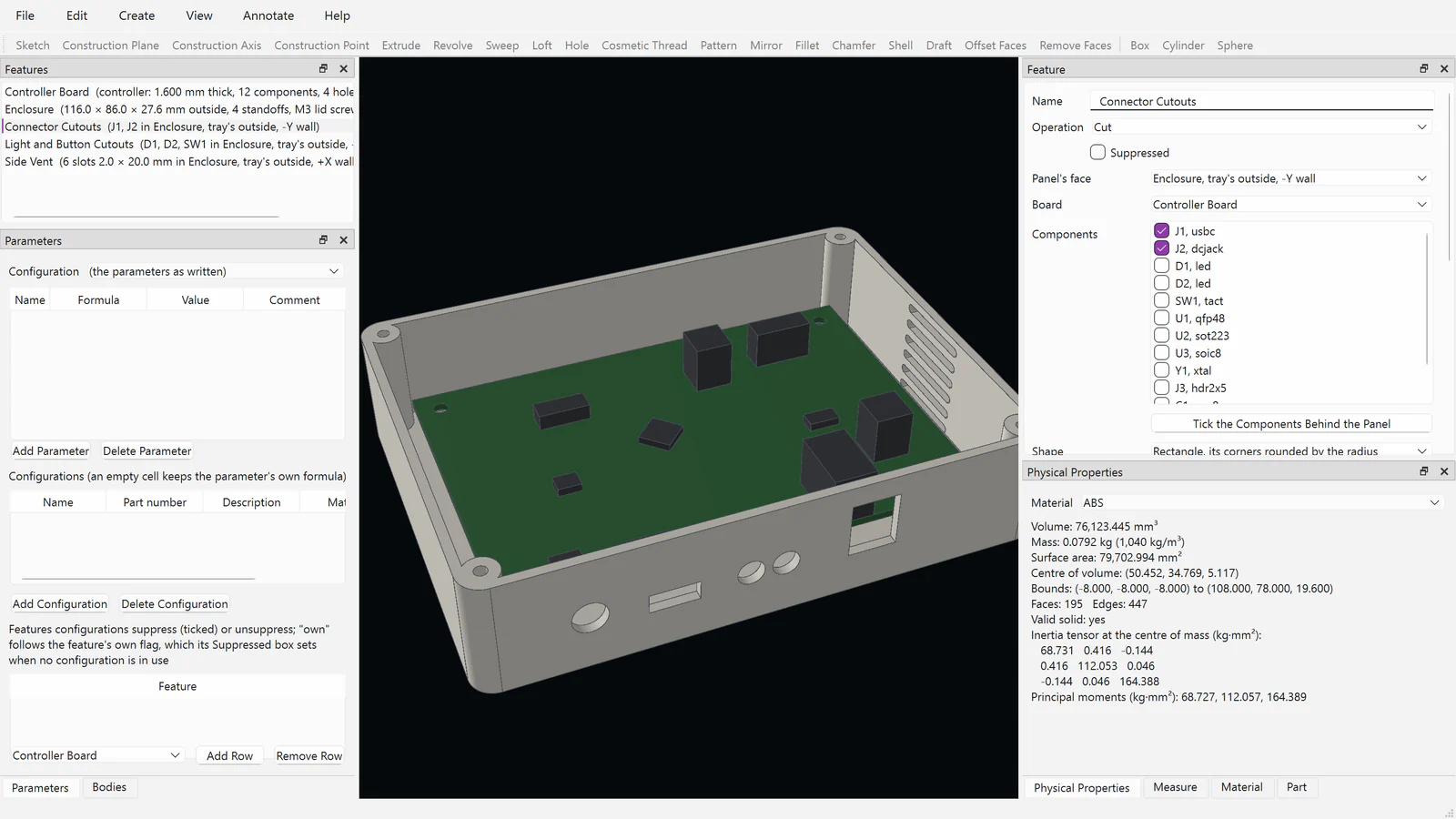
A screenshot of Fusion CAD's development build on Windows: an enclosure fitted round a circuit board, its cutouts following the board's connectors.
See Fusion CAD at work.
Every picture here is the development build's own window, opened on example parts, assemblies and drawings it made itself and photographed by it. Nothing is drawn by hand: the 3D view is Fusion 3D Engine's, and the numbers are the program's.56 seconds of Fusion CAD's own windows, captured from the development build. No sound.
Parametric parts
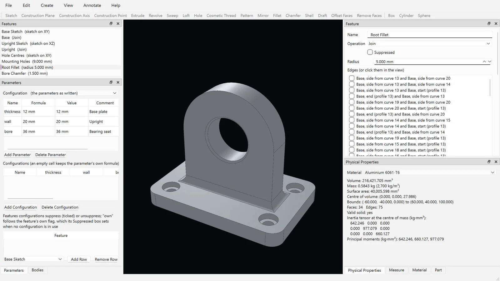
The bracket's history, parameters and fillet editor, with its mass and inertia.
Sheet Metal
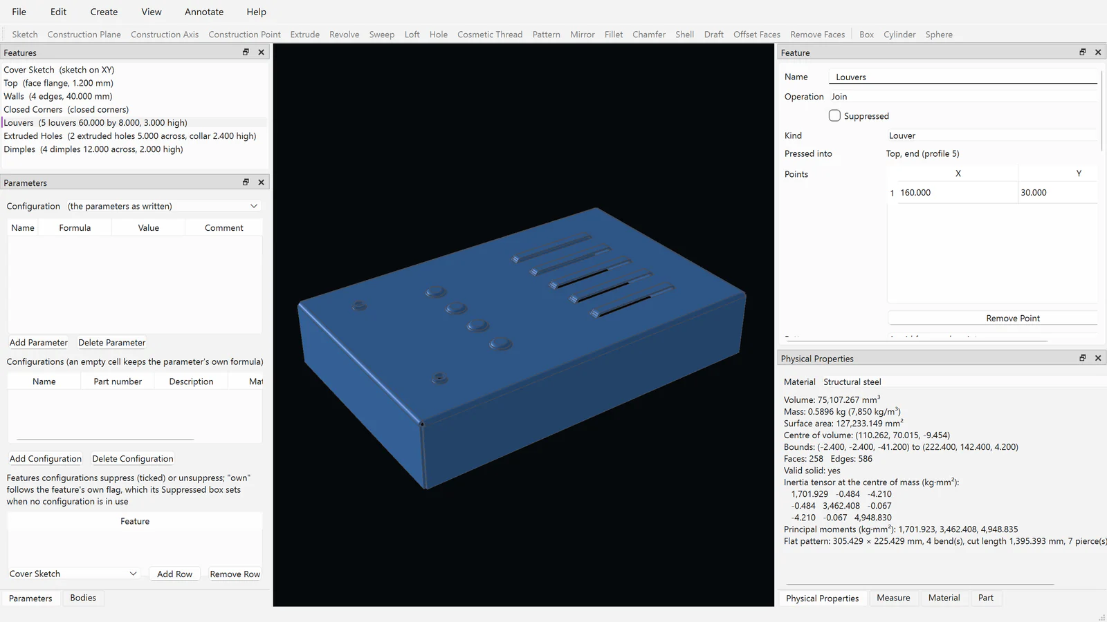
A steel cover with closed corners, louvers, dimples and extruded holes.
Flat patterns
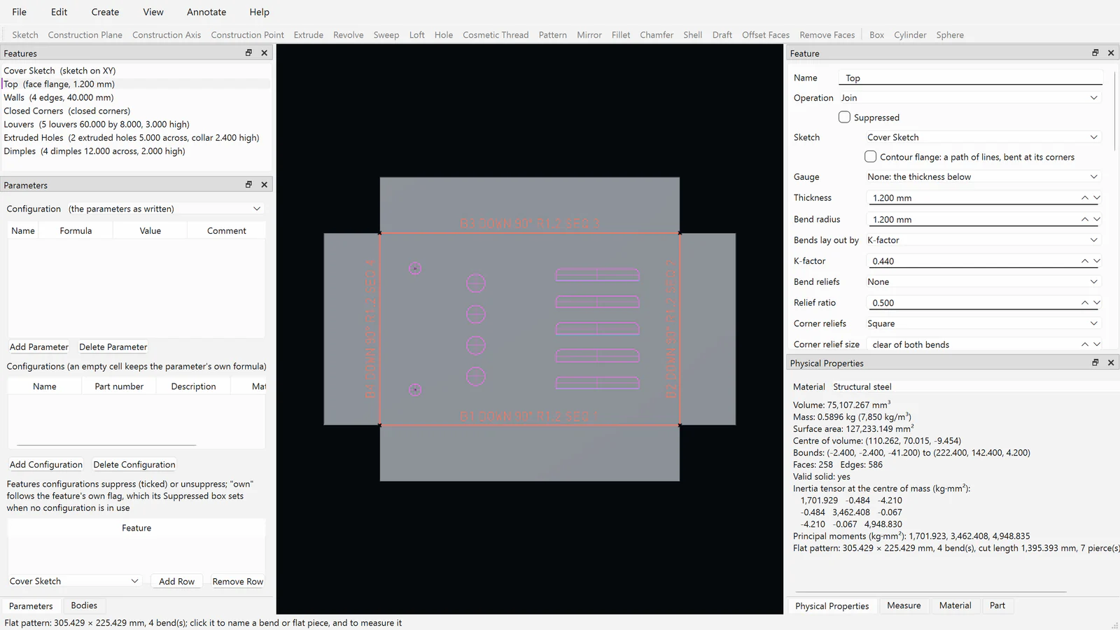
The same cover laid flat, each bend tagged with its direction, radius and order.
Nesting
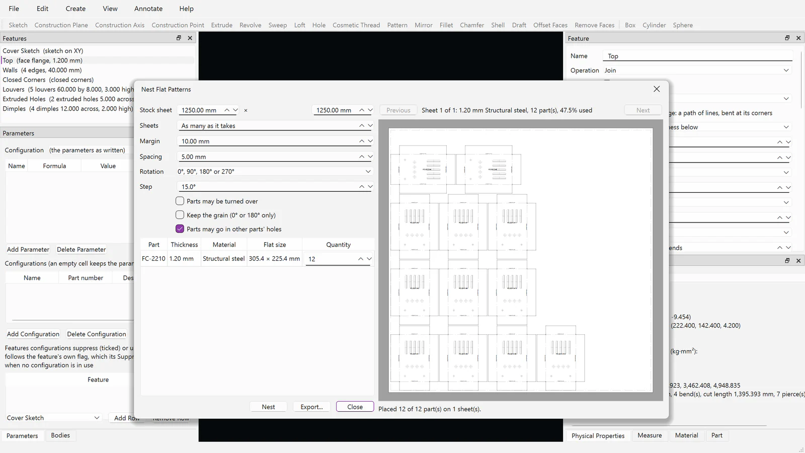
Twelve covers nested on a stock sheet, ready to export for cutting.
Weldments and Frames
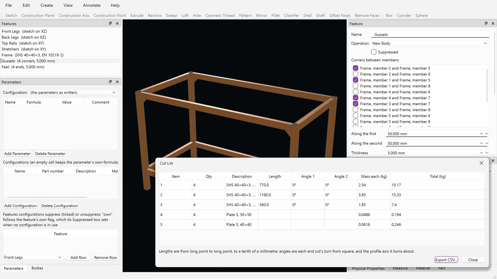
A bench frame of SHS 40×40×3 and its cut list, lengths long point to long point.
Assemblies and exploded views
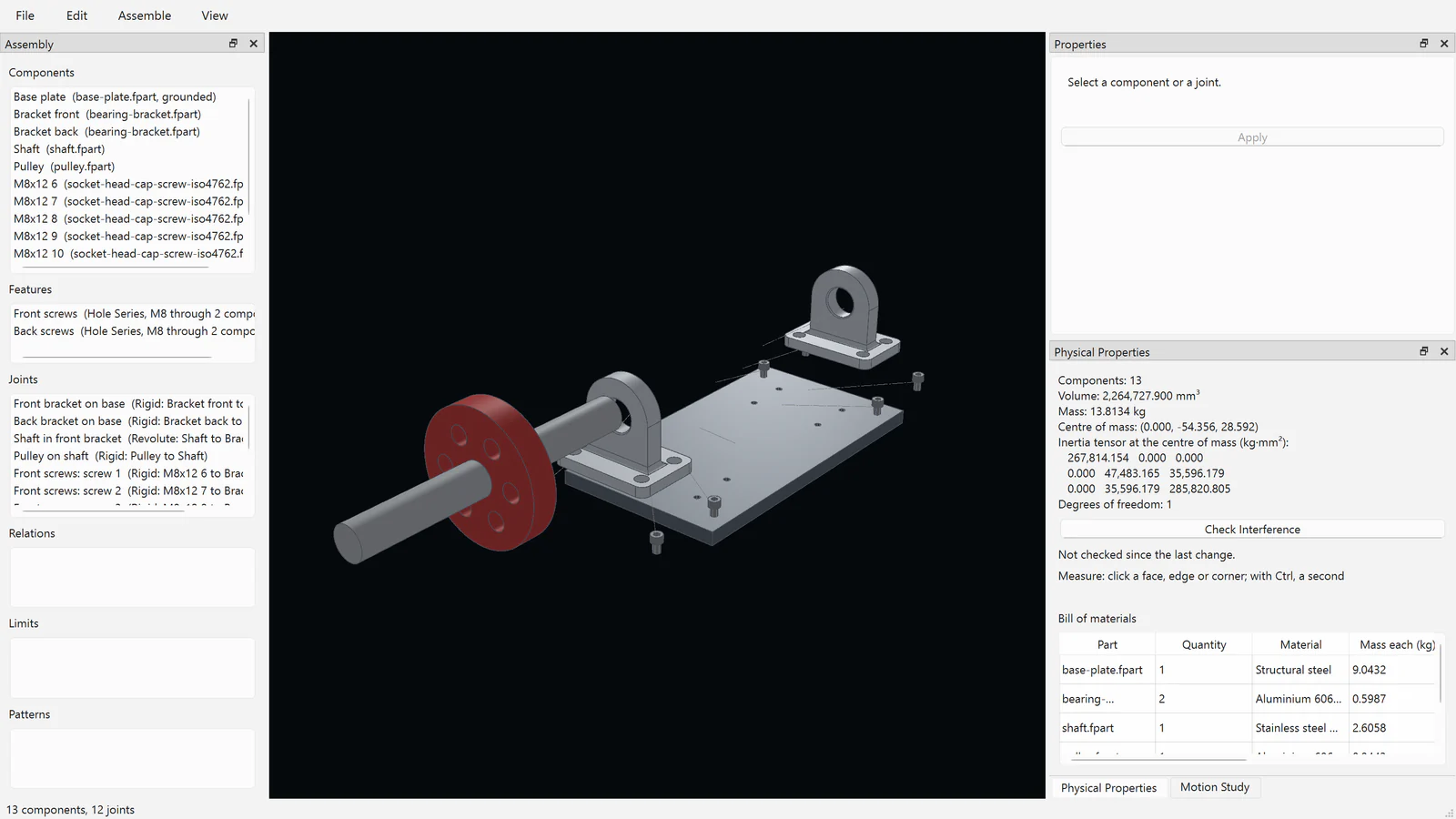
A shaft unit held by joints, its screws inserted by hole series, exploded with trails.
Advanced Surfacing
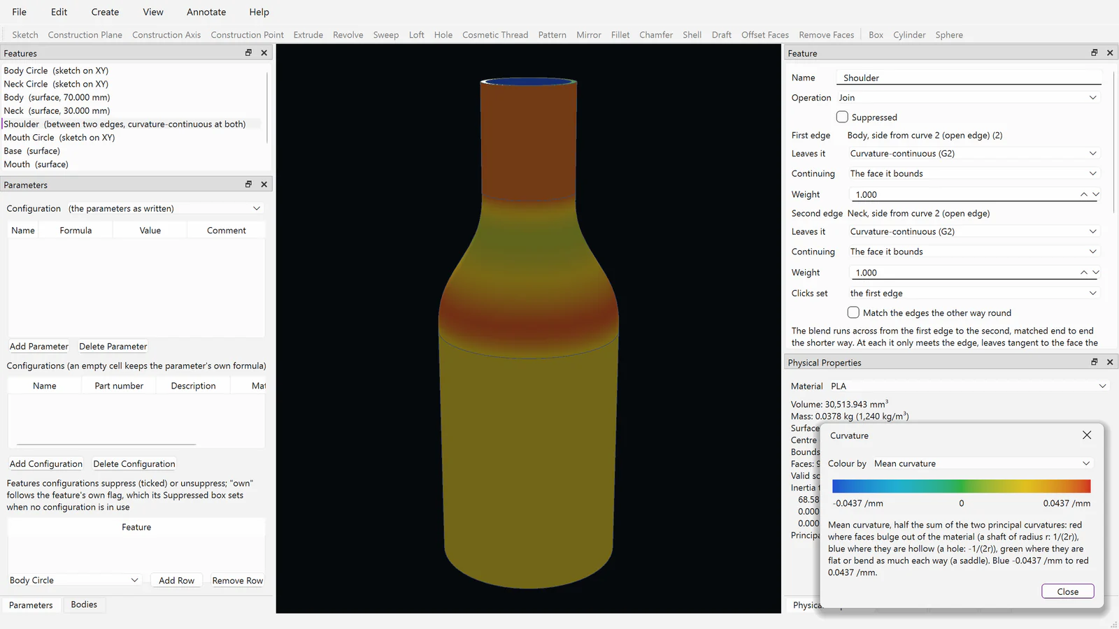
A bottle's G2 shoulder blend, coloured by its mean curvature.
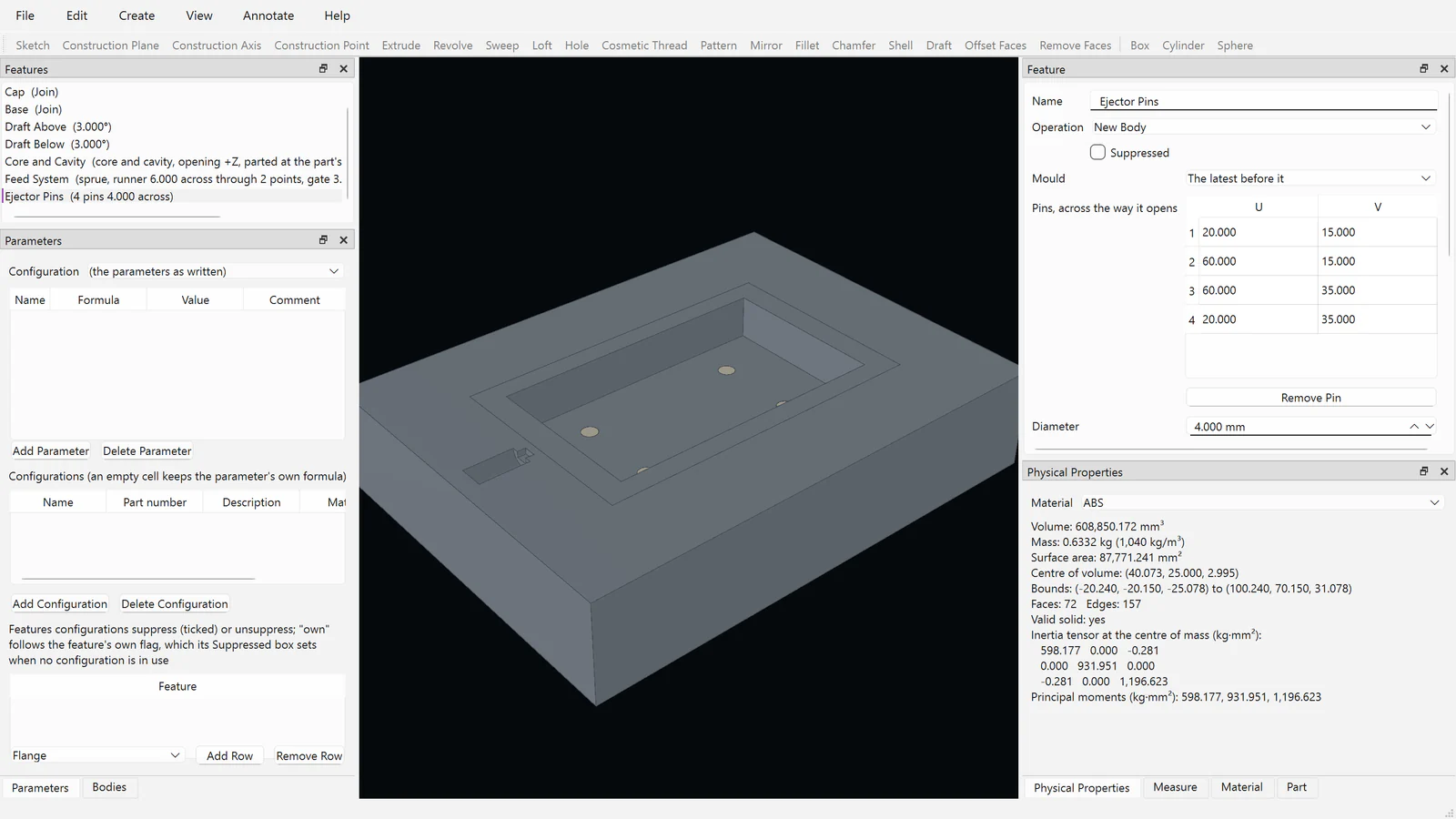
Mold and Plastic Parts
A mould's core with its impression, ejector pins, runner and gate.
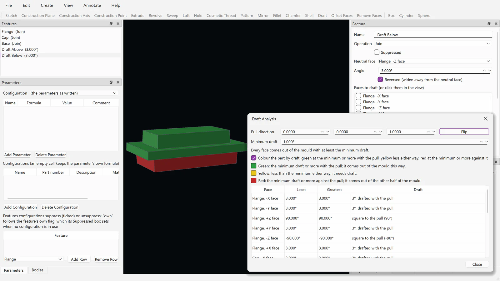
Draft analysis
The moulded cap coloured by draft: green with the pull, red against it.
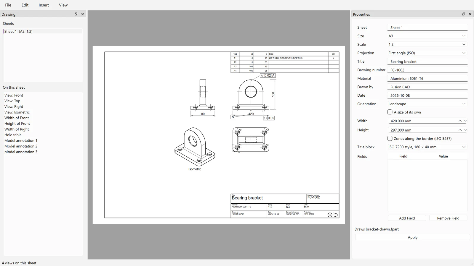
Drawings
An A3 sheet of the bracket with GD&T, a hole table and its title block.
From the first sketch to the finished assembly.
Sketches, parametric features, editable history, assemblies with joints, drawings and engineering checks stay connected the whole way through. Everything below runs in the development build on Windows and Fusion OS.
Sketches that keep their intent
IN DEVELOPMENTLines, arcs, circles, splines and ellipses with twenty kinds of constraints and dimensions, curvature-continuous joins, trim, extend and patterns. The solver moves geometry as little as it must and shows what is still free.
Parametric features
IN DEVELOPMENTExtrude, revolve, sweep and loft, holes with standard sizes and seats, shells, drafts, fillets with varying radii, chamfers, ribs, patterns, mirrors, text and wrap, all driven by parameters, formulas and configurations.
References that survive changes
IN DEVELOPMENTFaces, edges and corners are named by how they were made, so later features, assemblies, drawings and studies stay attached when the design changes.
Bodies and surfaces
IN DEVELOPMENTSeveral bodies in one part, combined, split, moved and scaled; surfaces extruded, revolved, patched, thickened and stitched; split lines for loads and parting lines.
Assemblies with joints
IN DEVELOPMENTSeven kinds of joint, gears, racks, screws and cams, distance and angle limits, flexible sub-assemblies, motion studies that stop where parts meet, exploded views and component patterns.
Hole series and standard parts
IN DEVELOPMENTHoles drilled through a stack of parts in the assembly, with ISO screws, nuts and washers inserted at a length that engages; threads shown as ISO 6410 draws them.
Drawings that follow the part
IN DEVELOPMENTStandard, section, detail, auxiliary and broken-out views; dimensions with ISO tolerances and fits; hole tables and callouts, parts lists, balloons and title blocks; PDF, SVG and DXF.
Engineering checks
IN DEVELOPMENTMass properties, interference, measurement, draft analysis, curvature and zebra stripes, and bills of materials, flat or indented.
Exchange and Pack and Go
IN DEVELOPMENTSTEP with colours and with GD&T as AP242 PMI, IGES, STL and 3MF in and out, and DXF into sketches. Pack and Go gathers a design with every file it uses.
Modules you add as your work needs them.
Fusion CAD is expanded with modules. Anyone can open, view, print and export what a module made; its licence is needed only to create and edit it. The modules are in development, and their names, editions and prices are not set.
Sheet Metal
IN DEVELOPMENTFlanges, hems, closed corners, sketched bends and jogs, miter flanges, lofted transitions and forming tools; flat patterns with bend tables and DXF, nested on stock sheets.
Weldments and Frames
IN DEVELOPMENTStructural members from checked steel and aluminium section tables, mitred, coped and stopped at junctions, with gussets, end caps, welds shown or modelled, and cut lists.
GD&T and Model-Based Definition
IN DEVELOPMENTDatums, feature control frames, surface texture and sizes with ISO fits on the model, checked against the rules, shown on drawings and written to STEP AP242.
Mold and Plastic Parts
IN DEVELOPMENTCore and cavity with shrinkage, draft and undercut warnings, mounting bosses, ejector pins and feed systems.
Advanced Surfacing
IN DEVELOPMENTFill and blend surfaces up to curvature continuity, offsets, extensions and trims, with curvature combs.
ECAD link
IN DEVELOPMENTCircuit boards read from IDF 3.0 with their components and keep-outs, as bodies of the part. A native link with Fusion EDA is planned.
Routing
IN DEVELOPMENTTube routes bent through points, with the bend data and table a tube bender needs.
Enclosures and Panels
IN DEVELOPMENTEnclosures fitted round a board, panel cutouts that follow its components, vents, lids with lips, screws or snap hooks, and panel drawings dimensioned from a datum.
Design files that keep the whole design.
Parts keep their full feature history, so a design can always be reopened, changed and rebuilt.
.fpart
A part: its sketches, features, parameters, configurations and the stable names of its faces and edges.
.fassembly
An assembly: the parts it uses, where they are placed, the joints between them and the features it cuts.
.fdrawing
A drawing of a part or assembly for manufacturing and review, following the part as it changes.
Designed to work with the rest of Fusion.
Fusion CAD's command line hands its parts to the other engineering products by the names of their faces, so loads, studies and toolpaths follow the design as it changes.
Fusion SIM
Meshes Fusion CAD parts for structural, thermal and dynamic studies, with loads and fixtures on named faces.fusionsim.cloud →
Fusion MAT
Drives Fusion CAD's parameters in sweeps and optimization, and measures each variant.fusionmat.cloud →
Fusion CAM
Reads Fusion CAD parts, with their edges, corners and threads, to plan toolpaths.fusioncam.cloud →
Fusion EDA
Boards come into Fusion CAD from IDF files today; a native link passing board outlines and components both ways is planned.fusioneda.cloud →
Fusion PDM
Check-out, check-in and versions from inside Fusion CAD, with every file an assembly uses.fusionpdm.cloud →
Fusion Canvas
Finishes painted in Canvas come back to the part's faces by name as colours and finishes.fusioncanvas.cloud →
Part of the Fusion platform.
Fusion 3D Engine
Fusion's core 3D engine draws Fusion CAD's 3D view, with colours by value for draft, curvature and zebra stripes.fusion3d.cloud →
Fusion OS
Fusion CAD is built in C++ to run natively on Fusion OS as well as on Windows, and passes the same tests on both.Fusion OS →
Vault
Keep design files safe with Vault's backup and storage products.fusionvault.cloud →